The software architecture defines the modular structure of the
BrewMaster Pro 3000’s embedded control system. The architecture
follows a layered approach with clear separation of concerns:
safety-critical functions are isolated in dedicated modules, control
algorithms are encapsulated for reusability, and user interface logic
is decoupled from core brewing operations. This modular design enables
independent testing, facilitates maintenance, and provides clear
interfaces between components.
The architecture emphasizes fail-safe design principles. The Safety
Monitor Module operates with the highest priority and can override all
other subsystems. Module dependencies are carefully managed to prevent
circular references and ensure deterministic behavior. The following
diagram shows the architectural modules and their relationships:
Module handling all user interactions including button debouncing, LED
status indicators, and display updates. Interfaces with the Brew
Controller to send user commands (strength selection, start/stop).
Module managing the brewing process state machine. States: IDLE,
HEATING, BREWING, COMPLETE, ERROR. Controls pump and valve timing
based on selected strength. Waits for temperature ready signal before
initiating brew cycle. Monitors safety status continuously.
The safety layer contains modules with the highest execution priority,
performing continuous safety monitoring and enforcing fail-safe
shutdown procedures.
Driver for PWM output generation. Controls the heating element via
variable duty cycle (0–100%) at 1 kHz switching frequency. Supports
soft-start ramp to prevent inrush current.
Driver for the SPI bus peripheral. Provides communication with the
front-panel display controller (OLED) for status and menu rendering.
Operates at 4 MHz with DMA for frame-buffer transfers.
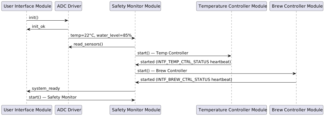
The sequence diagrams below show how the architectural components
interact at runtime. Participants map directly to the components
defined in the Static View.
The diagrams are generated by needsequence, which traverses the startup_calls
/ shutdown_calls links defined on each component need. Each seq_msg (SEQSTART_01)
need in the chain represents one message; odd hops are participants,
even hops are messages.
On power-on the system initialises hardware, validates initial sensor
readings, then brings all control modules online in dependency order
before signalling readiness to the user.
The sequence message needs (SEQSTART_01–SEQSTART_10) are
defined below. COMP_UI_MODULE is the starting participant.
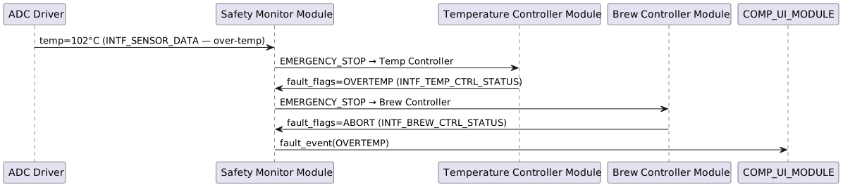
If the Safety Monitor detects an over-temperature condition it issues
an EMERGENCY_STOP command on INTF_SAFETY_CMD to all controlled
subsystems. All modules must respond within 100 ms.
The sequence message needs (SEQSHTDWN_01–SEQSHTDWN_06) are
defined below. COMP_ADC_DRV is the starting participant (it is the
source of the over-temperature sensor reading).
![@startuml
component "<size:12>Component</size>\n**User Interface**\n**Module**\n<size:10>COMP_UI_MODULE</size>" as COMP_UI_MODULE [[../coffee-machine/architecture.html#COMP_UI_MODULE]] #3498db
node "<size:12>SW_Requirement</size>\n**Button Input**\n**Handler**\n<size:10>SWREQ_BUTTON_INPUT</size>" as SWREQ_BUTTON_INPUT [[../coffee-machine/sw_requirements.html#SWREQ_BUTTON_INPUT]] #a8f578
interface "<size:12>Interface</size>\n**GPIO Interface**\n<size:10>INTF_GPIO</size>" as INTF_GPIO [[../coffee-machine/architecture.html#INTF_GPIO]] #16a085
interface "<size:12>Interface</size>\n**SPI Bus**\n**Interface**\n<size:10>INTF_SPI_BUS</size>" as INTF_SPI_BUS [[../coffee-machine/architecture.html#INTF_SPI_BUS]] #16a085
interface "<size:12>Interface</size>\n**User Command**\n**Interface**\n<size:10>INTF_USER_CMD</size>" as INTF_USER_CMD [[../coffee-machine/architecture.html#INTF_USER_CMD]] #16a085
SWREQ_BUTTON_INPUT <-- COMP_UI_MODULE
COMP_UI_MODULE --( INTF_GPIO
COMP_UI_MODULE --( INTF_SPI_BUS
COMP_UI_MODULE -- INTF_USER_CMD
@enduml](../_images/plantuml-6881aef3eeba1bef8ff6e4c9e7fcb89ad0adea9b.svg)
![@startuml
component "<size:12>Component</size>\n**Brew Controller**\n**Module**\n<size:10>COMP_BREW_CTRL</size>" as COMP_BREW_CTRL [[../coffee-machine/architecture.html#COMP_BREW_CTRL]] #3498db
node "<size:12>SW_Requirement</size>\n**Brew Strength**\n**Selection**\n<size:10>SWREQ_BREW_STRENGTH</size>" as SWREQ_BREW_STRENGTH [[../coffee-machine/sw_requirements.html#SWREQ_BREW_STRENGTH]] #a8f578
interface "<size:12>Interface</size>\n**GPIO Interface**\n<size:10>INTF_GPIO</size>" as INTF_GPIO [[../coffee-machine/architecture.html#INTF_GPIO]] #16a085
interface "<size:12>Interface</size>\n**Safety Command**\n**Interface**\n<size:10>INTF_SAFETY_CMD</size>" as INTF_SAFETY_CMD [[../coffee-machine/architecture.html#INTF_SAFETY_CMD]] #16a085
interface "<size:12>Interface</size>\n**Temperature**\n**Status**\n**Interface**\n<size:10>INTF_TEMP_STATUS</size>" as INTF_TEMP_STATUS [[../coffee-machine/architecture.html#INTF_TEMP_STATUS]] #16a085
interface "<size:12>Interface</size>\n**User Command**\n**Interface**\n<size:10>INTF_USER_CMD</size>" as INTF_USER_CMD [[../coffee-machine/architecture.html#INTF_USER_CMD]] #16a085
interface "<size:12>Interface</size>\n**Brew Controller**\n**Safety Status**\n**Interface**\n<size:10>INTF_BREW_CTRL_STATUS</size>" as INTF_BREW_CTRL_STATUS [[../coffee-machine/architecture.html#INTF_BREW_CTRL_STATUS]] #16a085
SWREQ_BREW_STRENGTH <-- COMP_BREW_CTRL
COMP_BREW_CTRL --( INTF_GPIO
COMP_BREW_CTRL --( INTF_SAFETY_CMD
COMP_BREW_CTRL --( INTF_TEMP_STATUS
COMP_BREW_CTRL --( INTF_USER_CMD
COMP_BREW_CTRL -- INTF_BREW_CTRL_STATUS
@enduml](../_images/plantuml-10fee869d07dba3c605f147d1ca1ec42596464a7.svg)
![@startuml
component "<size:12>Component</size>\n**Temperature**\n**Controller**\n**Module**\n<size:10>COMP_TEMP_CTRL</size>" as COMP_TEMP_CTRL [[../coffee-machine/architecture.html#COMP_TEMP_CTRL]] #3498db
node "<size:12>SW_Requirement</size>\n**Temperature**\n**Regulation**\n<size:10>SWREQ_TEMP_REGULATION</size>" as SWREQ_TEMP_REGULATION [[../coffee-machine/sw_requirements.html#SWREQ_TEMP_REGULATION]] #a8f578
interface "<size:12>Interface</size>\n**PWM Control**\n**Interface**\n<size:10>INTF_PWM_CTRL</size>" as INTF_PWM_CTRL [[../coffee-machine/architecture.html#INTF_PWM_CTRL]] #16a085
interface "<size:12>Interface</size>\n**Safety Command**\n**Interface**\n<size:10>INTF_SAFETY_CMD</size>" as INTF_SAFETY_CMD [[../coffee-machine/architecture.html#INTF_SAFETY_CMD]] #16a085
interface "<size:12>Interface</size>\n**Sensor Data**\n**Interface**\n<size:10>INTF_SENSOR_DATA</size>" as INTF_SENSOR_DATA [[../coffee-machine/architecture.html#INTF_SENSOR_DATA]] #16a085
interface "<size:12>Interface</size>\n**Temperature**\n**Controller**\n**Safety Status**\n**Interface**\n<size:10>INTF_TEMP_CTRL_STATUS</size>" as INTF_TEMP_CTRL_STATUS [[../coffee-machine/architecture.html#INTF_TEMP_CTRL_STATUS]] #16a085
interface "<size:12>Interface</size>\n**Temperature**\n**Status**\n**Interface**\n<size:10>INTF_TEMP_STATUS</size>" as INTF_TEMP_STATUS [[../coffee-machine/architecture.html#INTF_TEMP_STATUS]] #16a085
SWREQ_TEMP_REGULATION <-- COMP_TEMP_CTRL
COMP_TEMP_CTRL --( INTF_PWM_CTRL
COMP_TEMP_CTRL --( INTF_SAFETY_CMD
COMP_TEMP_CTRL --( INTF_SENSOR_DATA
COMP_TEMP_CTRL -- INTF_TEMP_CTRL_STATUS
COMP_TEMP_CTRL -- INTF_TEMP_STATUS
@enduml](../_images/plantuml-878559187874dc95a15806341d0c5556c5e22ae2.svg)
![@startuml
component "<size:12>Component</size>\n**Safety Monitor**\n**Module**\n<size:10>COMP_SAFETY_MON</size>" as COMP_SAFETY_MON [[../coffee-machine/architecture.html#COMP_SAFETY_MON]] #3498db
node "<size:12>SW_Requirement</size>\n**Over-**\n**Temperature**\n**Shutdown**\n<size:10>SWREQ_OVERTEMP_SHUTDOWN</size>" as SWREQ_OVERTEMP_SHUTDOWN [[../coffee-machine/sw_requirements.html#SWREQ_OVERTEMP_SHUTDOWN]] #a8f578
node "<size:12>SW_Requirement</size>\n**Water Level**\n**Monitoring**\n<size:10>SWREQ_WATER_LEVEL</size>" as SWREQ_WATER_LEVEL [[../coffee-machine/sw_requirements.html#SWREQ_WATER_LEVEL]] #a8f578
interface "<size:12>Interface</size>\n**Brew Controller**\n**Safety Status**\n**Interface**\n<size:10>INTF_BREW_CTRL_STATUS</size>" as INTF_BREW_CTRL_STATUS [[../coffee-machine/architecture.html#INTF_BREW_CTRL_STATUS]] #16a085
interface "<size:12>Interface</size>\n**Sensor Data**\n**Interface**\n<size:10>INTF_SENSOR_DATA</size>" as INTF_SENSOR_DATA [[../coffee-machine/architecture.html#INTF_SENSOR_DATA]] #16a085
interface "<size:12>Interface</size>\n**Temperature**\n**Controller**\n**Safety Status**\n**Interface**\n<size:10>INTF_TEMP_CTRL_STATUS</size>" as INTF_TEMP_CTRL_STATUS [[../coffee-machine/architecture.html#INTF_TEMP_CTRL_STATUS]] #16a085
interface "<size:12>Interface</size>\n**Safety Command**\n**Interface**\n<size:10>INTF_SAFETY_CMD</size>" as INTF_SAFETY_CMD [[../coffee-machine/architecture.html#INTF_SAFETY_CMD]] #16a085
SWREQ_OVERTEMP_SHUTDOWN <-- COMP_SAFETY_MON
SWREQ_WATER_LEVEL <-- COMP_SAFETY_MON
COMP_SAFETY_MON --( INTF_BREW_CTRL_STATUS
COMP_SAFETY_MON --( INTF_SENSOR_DATA
COMP_SAFETY_MON --( INTF_TEMP_CTRL_STATUS
COMP_SAFETY_MON -- INTF_SAFETY_CMD
@enduml](../_images/plantuml-c3da38b9ed86f5f670fe6103908d76fe61996b28.svg)
![@startuml
component "<size:12>Component</size>\n**ADC Driver**\n<size:10>COMP_ADC_DRV</size>" as COMP_ADC_DRV [[../coffee-machine/architecture.html#COMP_ADC_DRV]] #3498db
interface "<size:12>Interface</size>\n**Sensor Data**\n**Interface**\n<size:10>INTF_SENSOR_DATA</size>" as INTF_SENSOR_DATA [[../coffee-machine/architecture.html#INTF_SENSOR_DATA]] #16a085
COMP_ADC_DRV -- INTF_SENSOR_DATA
@enduml](../_images/plantuml-f330d7099bfbac875e24ccef89ac54a330b2c2db.svg)
![@startuml
component "<size:12>Component</size>\n**PWM Driver**\n<size:10>COMP_PWM_DRV</size>" as COMP_PWM_DRV [[../coffee-machine/architecture.html#COMP_PWM_DRV]] #3498db
interface "<size:12>Interface</size>\n**PWM Control**\n**Interface**\n<size:10>INTF_PWM_CTRL</size>" as INTF_PWM_CTRL [[../coffee-machine/architecture.html#INTF_PWM_CTRL]] #16a085
COMP_PWM_DRV -- INTF_PWM_CTRL
@enduml](../_images/plantuml-e934ab64cb2de6dfd1df59d816059135c8ff9894.svg)
![@startuml
component "<size:12>Component</size>\n**GPIO Driver**\n<size:10>COMP_GPIO_DRV</size>" as COMP_GPIO_DRV [[../coffee-machine/architecture.html#COMP_GPIO_DRV]] #3498db
interface "<size:12>Interface</size>\n**GPIO Interface**\n<size:10>INTF_GPIO</size>" as INTF_GPIO [[../coffee-machine/architecture.html#INTF_GPIO]] #16a085
COMP_GPIO_DRV -- INTF_GPIO
@enduml](../_images/plantuml-89bcc7568e6bbc6a89439cc80a7a7cda38a9eeba.svg)
![@startuml
component "<size:12>Component</size>\n**SPI Driver**\n<size:10>COMP_SPI_DRV</size>" as COMP_SPI_DRV [[../coffee-machine/architecture.html#COMP_SPI_DRV]] #3498db
interface "<size:12>Interface</size>\n**SPI Bus**\n**Interface**\n<size:10>INTF_SPI_BUS</size>" as INTF_SPI_BUS [[../coffee-machine/architecture.html#INTF_SPI_BUS]] #16a085
COMP_SPI_DRV -- INTF_SPI_BUS
@enduml](../_images/plantuml-60cd74fb0eeb083ad7ed5fb3613757232148461f.svg)
![@startuml
' Config
top to bottom direction
' Nodes definition
package "<size:12>Architectural Layer</size>\n**Application**\n**Layer**\n<size:10>LAYER_APP</size>" as LAYER_APP [[../coffee-machine/architecture.html#LAYER_APP]] #8e44ad{
'child needs:
component "<size:12>Component</size>\n**Brew Controller**\n**Module**\n<size:10>COMP_BREW_CTRL</size>" as COMP_BREW_CTRL [[../coffee-machine/architecture.html#COMP_BREW_CTRL]] #3498db
component "<size:12>Component</size>\n**User Interface**\n**Module**\n<size:10>COMP_UI_MODULE</size>" as COMP_UI_MODULE [[../coffee-machine/architecture.html#COMP_UI_MODULE]] #3498db
interface "<size:12>Interface</size>\n**Brew Controller**\n**Safety Status**\n**Interface**\n<size:10>INTF_BREW_CTRL_STATUS</size>" as INTF_BREW_CTRL_STATUS [[../coffee-machine/architecture.html#INTF_BREW_CTRL_STATUS]] #16a085
interface "<size:12>Interface</size>\n**User Command**\n**Interface**\n<size:10>INTF_USER_CMD</size>" as INTF_USER_CMD [[../coffee-machine/architecture.html#INTF_USER_CMD]] #16a085
}
package "<size:12>Architectural Layer</size>\n**Control Layer**\n<size:10>LAYER_CTRL</size>" as LAYER_CTRL [[../coffee-machine/architecture.html#LAYER_CTRL]] #8e44ad{
'child needs:
component "<size:12>Component</size>\n**Temperature**\n**Controller**\n**Module**\n<size:10>COMP_TEMP_CTRL</size>" as COMP_TEMP_CTRL [[../coffee-machine/architecture.html#COMP_TEMP_CTRL]] #3498db
interface "<size:12>Interface</size>\n**Temperature**\n**Controller**\n**Safety Status**\n**Interface**\n<size:10>INTF_TEMP_CTRL_STATUS</size>" as INTF_TEMP_CTRL_STATUS [[../coffee-machine/architecture.html#INTF_TEMP_CTRL_STATUS]] #16a085
interface "<size:12>Interface</size>\n**Temperature**\n**Status**\n**Interface**\n<size:10>INTF_TEMP_STATUS</size>" as INTF_TEMP_STATUS [[../coffee-machine/architecture.html#INTF_TEMP_STATUS]] #16a085
}
package "<size:12>Architectural Layer</size>\n**Safety Layer**\n<size:10>LAYER_SAFETY</size>" as LAYER_SAFETY [[../coffee-machine/architecture.html#LAYER_SAFETY]] #8e44ad{
'child needs:
component "<size:12>Component</size>\n**Safety Monitor**\n**Module**\n<size:10>COMP_SAFETY_MON</size>" as COMP_SAFETY_MON [[../coffee-machine/architecture.html#COMP_SAFETY_MON]] #3498db
interface "<size:12>Interface</size>\n**Safety Command**\n**Interface**\n<size:10>INTF_SAFETY_CMD</size>" as INTF_SAFETY_CMD [[../coffee-machine/architecture.html#INTF_SAFETY_CMD]] #16a085
}
package "<size:12>Architectural Layer</size>\n**Hardware**\n**Abstraction**\n**Layer**\n<size:10>LAYER_HAL</size>" as LAYER_HAL [[../coffee-machine/architecture.html#LAYER_HAL]] #8e44ad{
'child needs:
component "<size:12>Component</size>\n**ADC Driver**\n<size:10>COMP_ADC_DRV</size>" as COMP_ADC_DRV [[../coffee-machine/architecture.html#COMP_ADC_DRV]] #3498db
component "<size:12>Component</size>\n**GPIO Driver**\n<size:10>COMP_GPIO_DRV</size>" as COMP_GPIO_DRV [[../coffee-machine/architecture.html#COMP_GPIO_DRV]] #3498db
component "<size:12>Component</size>\n**PWM Driver**\n<size:10>COMP_PWM_DRV</size>" as COMP_PWM_DRV [[../coffee-machine/architecture.html#COMP_PWM_DRV]] #3498db
component "<size:12>Component</size>\n**SPI Driver**\n<size:10>COMP_SPI_DRV</size>" as COMP_SPI_DRV [[../coffee-machine/architecture.html#COMP_SPI_DRV]] #3498db
interface "<size:12>Interface</size>\n**GPIO Interface**\n<size:10>INTF_GPIO</size>" as INTF_GPIO [[../coffee-machine/architecture.html#INTF_GPIO]] #16a085
interface "<size:12>Interface</size>\n**PWM Control**\n**Interface**\n<size:10>INTF_PWM_CTRL</size>" as INTF_PWM_CTRL [[../coffee-machine/architecture.html#INTF_PWM_CTRL]] #16a085
interface "<size:12>Interface</size>\n**Sensor Data**\n**Interface**\n<size:10>INTF_SENSOR_DATA</size>" as INTF_SENSOR_DATA [[../coffee-machine/architecture.html#INTF_SENSOR_DATA]] #16a085
interface "<size:12>Interface</size>\n**SPI Bus**\n**Interface**\n<size:10>INTF_SPI_BUS</size>" as INTF_SPI_BUS [[../coffee-machine/architecture.html#INTF_SPI_BUS]] #16a085
}
' Connection definition
COMP_UI_MODULE -[dashed]-( INTF_GPIO: uses\n
COMP_UI_MODULE -[dashed]-( INTF_SPI_BUS: uses\n
COMP_BREW_CTRL -[dashed]-( INTF_GPIO: uses\n
COMP_BREW_CTRL -[dashed]-( INTF_SAFETY_CMD: uses\n
COMP_BREW_CTRL -[dashed]-( INTF_TEMP_STATUS: uses\n
COMP_BREW_CTRL -[dashed]-( INTF_USER_CMD: uses\n
COMP_TEMP_CTRL -[dashed]-( INTF_PWM_CTRL: uses\n
COMP_TEMP_CTRL -[dashed]-( INTF_SAFETY_CMD: uses\n
COMP_TEMP_CTRL -[dashed]-( INTF_SENSOR_DATA: uses\n
COMP_SAFETY_MON -[dashed]-( INTF_BREW_CTRL_STATUS: uses\n
COMP_SAFETY_MON -[dashed]-( INTF_SENSOR_DATA: uses\n
COMP_SAFETY_MON -[dashed]-( INTF_TEMP_CTRL_STATUS: uses\n
INTF_USER_CMD -[bold]- COMP_UI_MODULE: provided by\n
INTF_BREW_CTRL_STATUS -[bold]- COMP_BREW_CTRL: provided by\n
INTF_TEMP_STATUS -[bold]- COMP_TEMP_CTRL: provided by\n
INTF_TEMP_CTRL_STATUS -[bold]- COMP_TEMP_CTRL: provided by\n
INTF_SAFETY_CMD -[bold]- COMP_SAFETY_MON: provided by\n
INTF_PWM_CTRL -[bold]- COMP_PWM_DRV: provided by\n
INTF_GPIO -[bold]- COMP_GPIO_DRV: provided by\n
INTF_SPI_BUS -[bold]- COMP_SPI_DRV: provided by\n
INTF_SENSOR_DATA -[bold]- COMP_ADC_DRV: provided by\n
@enduml](../_images/plantuml-2bbc42eac599c29a84201942c14d91f474a0486a.svg)